WP1000/1100 DC Brushless Motor & Gear

Geared motor Specification
Scroll Table
| Geared motor code | PM | PD | PL (WP1100 only) |
|---|---|---|---|
| Configuration | Brushless motor & 1:64 Gear head |
Brushless motor & 1:42 Gear head |
Brushless motor & 1:8 Gear head |
| Operation voltage *1 | DC16V to DC24V | DC16V to DC24V | DC16V |
| Rated current *2 | Less than 300mA | Less than 400mA | Less than 700mA |
| Motor speed (rpm) | Approx. 50 to 70rpm at DC16 to 24V (100mNm Load) |
Approx. 75 to 110rpm at DC16 to 24V (100mNm Load) |
Approx. 348rpm at DC16V (100mNm Load) *3 |
| Direction of rotation | CW | ||
| Motor rated temperature | less than 70℃ (158℉) When the motor reaches a predefined temperature, power to the motor will shut off automatically. The operation of a motor that has shut down due to high temperature cannot be guaranteed. |
||
| Motor stall protection | 2sec TYP When the motor stalls, power to the motor will shut off within 15 seconds |
||
| Motor life *3 | 5,000hrs | ||
*1.The minimum operating voltage may vary depending on tube size, material, operating environment, and other factors. Please verify performance under actual operating conditions.
*2.The specified current consumption reflects normal operating conditions. Upon startup, an inrush current approximately three times greater than the normal value may be generated.
*3.The life of motor is based on laboratory test at WELCO and not gurateed value.
Flow amount benchmark (flow amount per rotation)
Scroll Table
| Inside diameter of tube (inches) |
1.6mm (1/16”) |
2.4mm (3/32”) |
3.2mm (1/8”) |
4mm ( - ) |
4.8mm (3/16”) |
6.4mm (1/4”) |
||||||
|---|---|---|---|---|---|---|---|---|---|---|---|---|
| Number of rollers | 2 | 4 | 2 | 4 | 2 | 4 | 2 | 4 | 2 | 4 | 2 | - |
| WP1000 Flow amount (mL) | - | 0.2 | 0.5 | 0.45 | 0.9 | 0.8 | 1.45 | 1.2 | 1.95 | 1.6 | 3.0 | - |
Note: Tube type F3/16”, EL1/8", EL3/16” and U3/16” cannot be used with four rollers due to its high hardness.
1. The flow amount rotation is based on laboratory test at WELCO. This may vary depending on operating environment, lot tolerances, and other factors. Please veryfiy performance under actual operation conditions.
2. The reference flow rate of the pump is determined by the product of flow amount per rotation and motor speed.
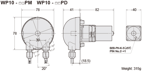
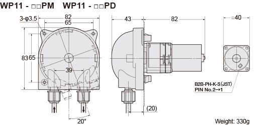
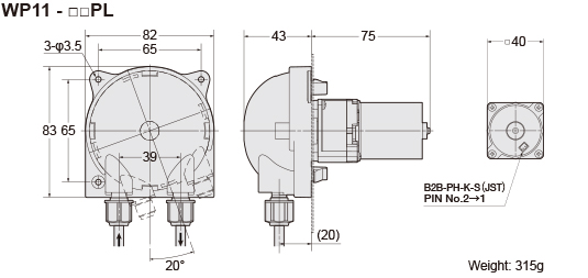
Dimensions (unit: mm)

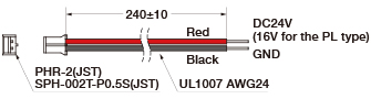
Motor wiring
Circuit protection
The motor rotates in one direction only: clockwise (CW). Overvoltage or incorrect connection of the positive and negative terminals may result in motor damage.
To prevent damage, please ensure that the input voltage remains within the rated voltage and that reverse polarity is avoided.